Introduction
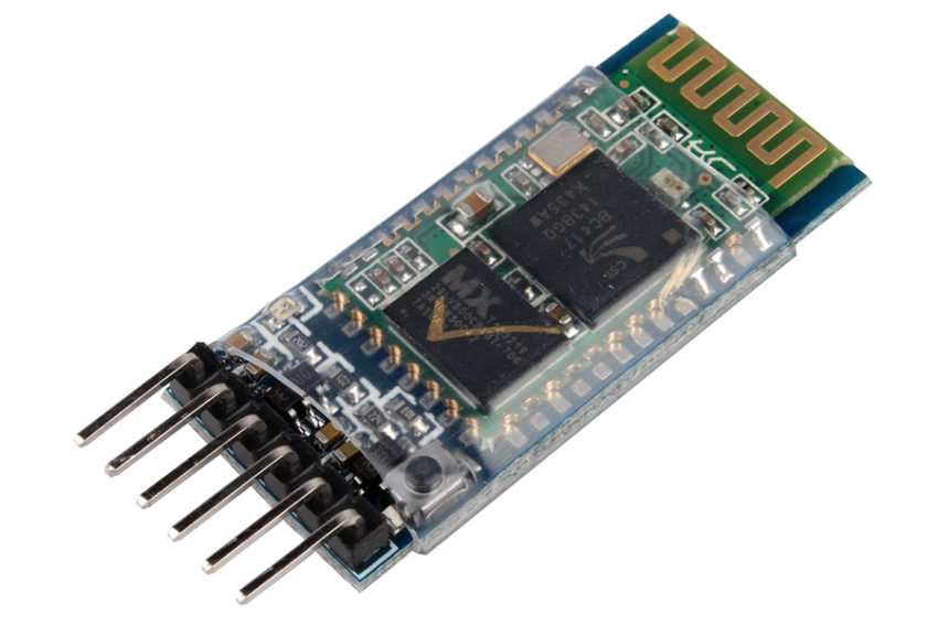
Today I will cover the popular HC-05 module. HC-05 is a Bluetooth 2.0 device that you can hook up to your Arduino to enable wireless communication. At the time of writing you can buy them on eBay for around €5. There is also a variant of this module called HC-06. The difference between them is that HC-06 can not be set in “master” mode and can not initiate a connection. So it’s not an upgrade which the name might suggest! HC-05 can be put in both “master” and “slave” mode and there is not really a big price difference so I would recommend getting the HC-05.
Setup
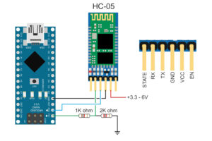
Before connecting these modules you need to know that even though the VCC is rated at 5V, the other pins are not! You may fry your device if you connect the IO pins to 5V. If you’re connecting your HC-05 to a 5V source, like an Arduino, you need to use a voltage divider on the RX pin to take it down to 3.3V. You don’t need to do this on the TX pin since it’s sending it’s 3.3V TO the Arduino, not receiving it.
- Connect the TX pin of the HC-05 to pin 10 of the Arduino.
- Connect the RX pin of the HC-05 to pin 11 of the Arduino (via the voltage divider).

Once you have hooked up the HC-05 to the Arduino like on the illustration above, you can send commands to it. But before the module will accept these commands, you will have to put it into it’s “AT mode”. To do this you press and hold the reset button located in the lower right corner of the device before supplying power to it. Once it starts blinking with an interval of about 2 seconds you can let go of the button.
The next step is to start the Arduino IDE. Then go on and load the sketch under File – Examples – SoftwareSerial – SoftwareSerialExample. You might need to change a few settings here, depending on your module’s settings. In my sketch the following row:
mySerial.begin(4800);
should be changed to a baud rate of 38400, since that is the default command baud rate of this module. Please note that the command baud rate can (and probably is) different from the UART baud rate.
When this is done, you should go ahead and upload the sketch to your Arduino.
Next open up the Serial Monitor and make sure that the baud rate in the lower bottom corner is set to the same as the Serial.begin(57600) statement in your sketch. In my version of the sketch, it’s set to 57600 baud, so that’s what I choose. You also need to choose “Both NL & CR” from the line ending drop down for the commands to work.
If the “Goodnight moon!” text located in the setup part of the sketch shows up correctly, you know that the baud rate between the PC and the Arduino is correct.
If you’re with me so far, try typing the command AT into the text box and hit enter. If everything works, you should get a response in the text area that simply says OK. If this is not the case, check the connections carefully and that the baud rates are correct. If you’re getting weird characters in the output window, the most common reason is the baud rate being wrong. If you don’t know the baud rate of your module, you can try the ones in the drop down list in the serial monitor. If the setup text “Goodnight moon!” shows up fine but the AT command is not working, it’s the mySerial.begin(38400) baud rate you need to change.
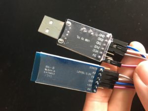
I would recommend getting a USB to TTL device like the CH340G that you can buy on eBay for just a couple of bucks. Then you don’t have to worry about the software part or the Arduino at all, you just hook the HC-05 up to the VCC, GND, RX and TX of the CH340G module and send the commands to that COM port the same way as described above.

Connecting two modules
In my Weather Station project I wanted to send a simple text string back to my PC to save into a database for a more grahical (and historical) representation of the collected data. First off I connected one HC-05 in “slave mode” to the CH340G module I mentioned before. I now have a COM port I can read the data from, perfect!
The next step was to connect the other HC-05 to an Arduino at the remote location (my balcony) in “master mode”. This is the way you set that up using AT commands:
The slave module:
- AT (make sure the device is responding with OK).
- AT+RMAAD (clear any previously paired devices)
- AT+ADDR? (get the address to the slave which we’ll use later)
- AT+ROLE=0 (set the module in slave mode)
- AT+PSWD=1234 (set a 4 digit pin code)
- AT+UART=9600,0,0 (set the speed)
- AT+RESET (reset the module to exit AT mode)
Then leave the module, which should be blinking the led at a faster rate.
The master module:
- AT (make sure the device is responding with OK).
- AT+RMAAD (clear any previously paired devices)
- AT+ROLE=1 (set the device in master mode)
- AT+PSWD=1234 (set a 4 digit pin code)
- AT+CMODE=0 (tells the device to connect to a specified address)
- AT+BIND=xxxx,xx,xxxxxx (set the address of the slave module)
Important: Make sure you use “,” instead of “:” as separator in this command. - AT+UART=9600,0,0 (set the speed)
- AT+RESET (reset the module to exit AT mode)
If you successfully entered all these commands correctly, after resetting the devices, they should now pair up. You will notice this by the lights of both modules blinking syncronised after a little while. When the modules are connected and out of AT mode, you can use the serial monitor of the Arduino IDE to send strings of text back and forth!
An easy way of reading the serial port data coming back on the slave module on Linux is to use screen like this:
screen /dev/ttyUSBx 38400
Where x is the mapped port number. You can see all available ports by issuing this command:
ls /dev/ttyUSB*
If you’re getting an error saying you don’t have permission, you need to add your user to the dialout group like this:
sudo usermod -a -G dialout $USER
Power consumption
The two modules I’m connecting here are already paired, and the video shows how fast they are connecting and what the current draw is during this process and once they are connected. As you can see, when the modules are connecting, the current draw rises to around 35mA. Once it’s connected and settles the current draw drops to around 4-6mA.
Thoughts
The HC-05 is a nice little module for easilly adding wireless communication to your project! It might seem a little difficult with the pairing and all the commands at first, but it’s really not that complicated.
The power consumption of the device is much better than say an ESP8266 WiFi module and it is much easier to use if the only thing you want to do is send some data to your PC.
The HC-05 is not a new module in 2018. It’s successor the HM-10 module has advantages like pairing speed, much lower current draw and more features like iBeacon for example. But there are a few things that bugs me with the HM-10 that the HC-05 does not suffer from, and if you can live with the higher current draw and pairing time it might still be a better choice.
I will write a similar review on the HM-10, but the things that bugs me compared to the HC-05 are:
- The state pin on the HC-05 behaves like you would expect. It goes HIGH only when the device is connected. On the HM-10, the state pin in it’s default mode (firmware v604) turns on and off at 500ms interval when no device is connected, same as the LED. In fact on the modules I have (both clones and genuine) they seem to be hard wired together. You can change this behaviour by issuing the command: AT+PIO11. This will change the behavior of the pin AND the led to go HIGH when a device is connected. But also, when no device is connected the pin and LED will be completely turned off, which is not great. There are discussions out there on this topic and it might have to do with your exact board as well since there are so many clones and bad copies of this board. Check out this link written by George Marzloff on the topic that has some different solutions to the issue.
- The separate AT mode. As you’ve seen in this article the HC-05 can be put in AT mode by pressing the reset button before supplying power. On the HM-10 the module is always in AT mode unless it’s connected. This can be confusing and potentially dangerous since you think you might be sending text, but the module is in AT mode. I strongly prefer the separate AT mode on the HC-05.
Datasheet: EC05

3 thoughts on “HC-05 review”